18+ Battery Charger Diagram Circuit
Both zener diodes can be 47V 12 watt. Web In this 12V Ni-Cd charger circuit a voltage doubler based on the popular 555 IC is used.

Simple Car Battery Charger And Indicator Circuit Diagram
In this tutorial we will take a look at charging circuits for sealed lead acid SLA Nickel Cadmium NiCd Nickel Metal Hydride NiMH and Lithium Polymer LiPo batteries.

. This circuit will help revive batteries that you think are dead or so old that they can no longer be reused. This automatic battery charger circuit is mainly involves two sections power supply section and load comparison section. The preset 10k preset.
The charger is powered by a 18 V AC 500 mAh transformer. This circuit can be used to charge all type of 12V rechargeable batteries including car batteries. Because output 3 of the chip is connected alternately between the 12 V supply voltage and earth the IC oscillates.
The wiring diagrams can be purchased from an online store or they may be obtained from a local electronics supply store. This circuit has two main parts one is the battery charging circuit and the second is DC to DC boost converter part. Web This is a simple Li-ion battery charger circuit with an automatic cut-off when fully charged.
They are high-quality chargers and are popular for charging lead-acid batteries. Zener resistor 10k. Web Learn about multi-stage battery chargers how theyre used and the circuit diagrams needed to build one yourself.
To limit confusion obscure details are kept archived at the tech support offices. The wiring diagram will provide the user with a detailed description of the connections and components needed for the. Here the output voltage is decided by the resistor values R1 and R2 in our case the resistor R2 is used as a variable resistor to control the output voltage.
Web Posted by Graham Lambert DIY Electronics 2. A simple Voltage Regulator Circuit taken from LM317s datasheet is shown in the figure above. Web Ni-Cd Slow Charger Circuit Diagram and Explanation.
Not only does it offer convenient and safe charging but it also allows. C 3 gets charged through D 2 and D 3 to almost 12 V when pin 3 is a logic low. These are our most commonly requested wiring diagrams suitable for typical customer needs.
In this post we learn how to build and use a 18V battery charger circuit for a cordless drill machine. Feel free to contact us with these requests. The Booster part is used to boost the battery voltage from 37v to 45v-6v.
Hareendran - 03062014 Here is a tried and tested sample circuit of a Li-Ion battery charger that can be used to 6V 24V 48V External Battery Charger Control Jim Keith - 12102013 This is an extension of the previously published External Battery Charger Control 12V. It is implemented by using the adjustable voltage regulator LM317. The circuit diagram for 18650 Lithium Battery Charger Booster Module is given above.
Web Overvoltage charging Normally the battery manufacturer usually prints the appropriate voltage. The below circuit diagram shows the battery charger circuit with the auto cut-off feature. Project Three-stage battery chargers are commonly referred to as smart chargers.
For instance there will be one or multiple LEDs that indicate when the charging is complete. Web Peak voltage detection is used in the constant current regulator CCR battery charging circuit shown below. Web Hello I just opened up the charger for my Skil screwdriver the battery is 144V and 12 Ah.
Web This 50a battery charger circuit diagram will contain an overall description of the item For use with 36 volt 18 cell series connected 180-350 amp-hour liquid. We should use a constant voltage charge. 12 volt 5 watt solar panel is the renowned part of this circuit.
Nowadays most of the batteries use the auto cut-off circuit. We made the circuit with commonly used components such as the NE555 timer and TL431 shunt regulator. At the initial stage1 we see that the battery voltage rises from 025 V to 40 V level in around one hour at 1 amp constant current charging rate.
Web An 18 volt battery charger circuit diagram displays the arrangement of each component. The main supply voltage 230V 50Hz is connected to the primary winding of the center tapped transformer to step down the voltage to 15-0-15V. We will provide schematics and instructions on how to build them.
Web So heres the completed customized battery charger circuit which can be used for charging any desired battery after setting it up as explained in our entire tutorial. Web Here is the circuit diagram of a simple and straight forward 12 V battery charger circuit with diagram. Web Overall the 18v Nicd Battery Charger Circuit is a great choice for anyone looking to power their project with a reliable and powerful energy source.
12V battery maximum voltage of 148V Standby use is 138V 6V battery maximum voltage of 75V Standby use is 68V High current fast charge But hot So you should use initial current less 30. The circuit is nothing but a 12V DC power supply with an ammeter for monitoring the charging current. We will gradually be adding additional relevant information to the list.
It also shows their relationship to each other the direction of current flow and the roles the components play. Web Circuit Diagram of Automatic Battery Charger. Web 18V Cordless Drill Battery Charger Circuit.
A step down AC transformer with the rating of 230V to 15V 1Amps is used here. The idea was requested by Mr. Even though the output current capacity of transformer is at 1Amps the allowable continuous current is only 04Amps for safe operation.
Using a peak voltage detection point of 15 Vcell will result in charging to about 97 of full capacity for NiMH and NiCd batteries. Web Lithium Ion Battery Charger Circuit with Diagrams TK. Web The following graph suggests the ideal charging procedure of a standard 37 V Li-Ion Cell rated with 42 V as the full charge level.
What I learned in broad strokes is that the Dewalt charger applies a constant current of 4A until the output reaches around 19V then it switches to a constant. The opamp can be a IC 741. Web In order to construct a lithium battery UPS charger circuit the first step is to obtain a wiring diagram.
Block diagram of simple constant current regulator battery charging circuit. The big resistance is around 13 ohms the circuit has the diode and the led and 2 small resistors but also a transistor connected somehow to the led. Web Heres a rudimentary diagram of my setup.
Web Circuit Diagram and Explanation. Web Voltage Regulator Circuit. Web The auto cut off is the most important parameter of the battery charging.
Web Battery Charger Wiring Diagrams.

Adjustable Regulated Battery Charger Electronic Schematic Diagram
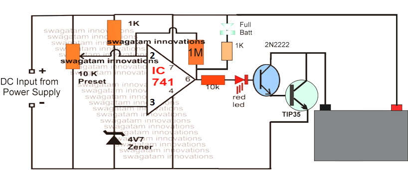
Automatic Universal Battery Charger Circuit For All Types Of Battery

Battery Charging Trickle Charging Onboard
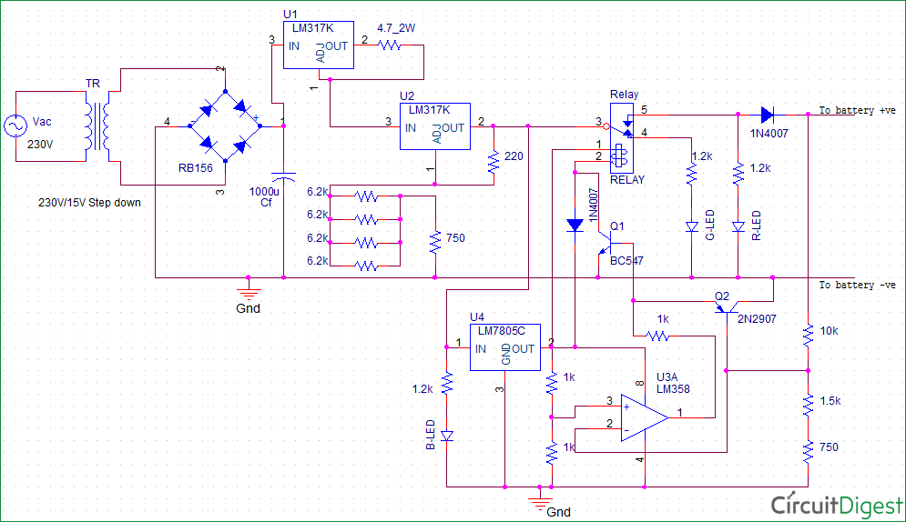
Float Charger Circuit Diagram For 12v Sla Battery
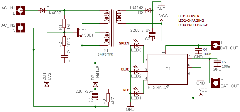
Li Ion Universal Battery Charger Teardown Codrey Electronics

31 Battery Charger Circuit Ideas Battery Charger Circuit Electronics Circuit Circuit
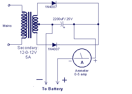
Battery Charger Circuit Make A 12v Battery Charger At Home

2x Plastic Case Charging Protection Circuit Board Pcb For Makita 18v Battery Bl1840 Bl1850 Bl1830 Bl1860b Lxt 400 On Onbuy
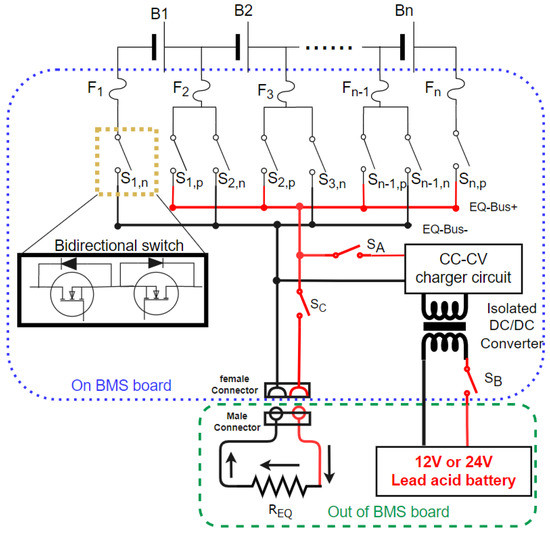
Energies Free Full Text A Cost Effective Passive Active Hybrid Equalizer Circuit Design
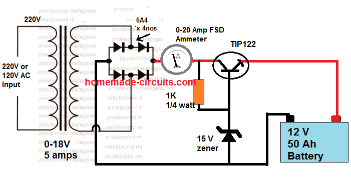
12v Battery Charger Circuits Using Lm317 Lm338 L200 Transistors Homemade Circuit Projects
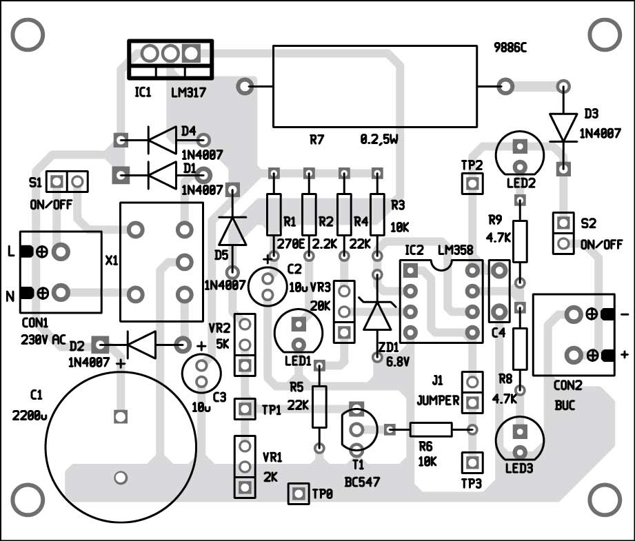
Battery Charger Circuit Full Diy Electronics Project
24v 5a Smart Charger For Lithium Lifepo4 Deep Cycle Rechargeable Batteries Expertpower Direct
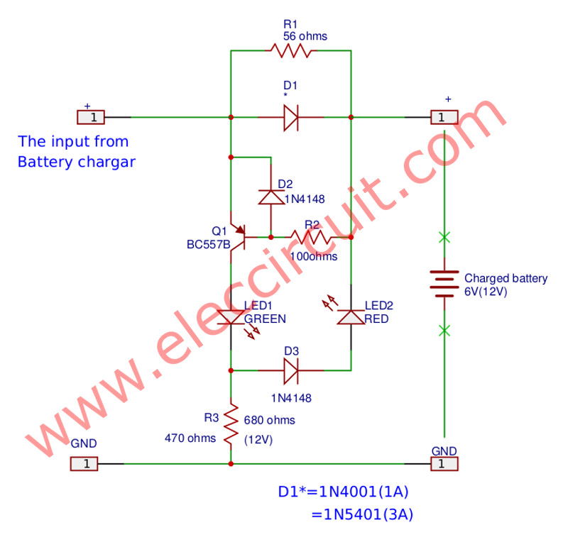
Battery Full Charge Alarm Circuit Eleccircuit Com
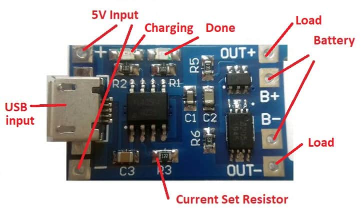
A Guide To Building Battery Chargers Circuit Basics
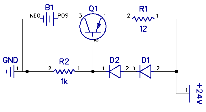
A Guide To Building Battery Chargers Circuit Basics
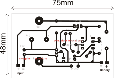
18v Cordless Drill Battery Charger Circuit Homemade Circuit Projects
What Happens To The Power That Batteries Supply If Short Circuited Quora